Question
Question: A series RLC circuit is made as shown in the figure with an AC source of 60 V, 20 Hz. Then 
This question has multiple correct options
A. The rms current through the resistor R is 4.2 A
B. The effective potential difference between P and Q should be 42 V.
C. The instantaneous current leads the source voltage by 45∘
D. The instantaneous current lags behind the applied voltage by 45∘
Solution
First calculate the impedance of the circuit . Then calculate the rms current through the resistor which is given by the ratio of rms voltage and the impedance. After that calculate the potential difference between the points P and Q. See the phase difference between the instantaneous current and source. Then compare all the results to see which option is correct.
Formulas used:
The impedance of the circuit is given by
Z=R2+(XL−XC)2
Where R the resistance of the circuit, XL is the inductive reactance and XC is the capacitive reactance.
Irms=ZVmax
tanϕ=RXL−XC
Where ϕ is the angle between current and voltage. Or phase difference
Complete answer:
Given the emf of the ac source is of 60V and the frequency is 20Hz.
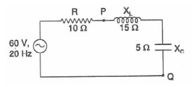
So Vmax=60V and frequency,f=20Hz
So the angular frequency
ω=2πf=40π
Now
Z=R2+(XL−XC)2=100+(15−5)2=200=102 Ω
Now the root mean square current is given by
Irms=ZVmax=10260=26=32=3×1.141=4.2A
So the option A is correct.
The equivalent reactance between the point P and Q is
R′=XL−XC=15−5=10Ω
So the potential difference between the points P and Q is
V=IR′=4.2×10=42V
So the option B is also correct.
The phase difference between the current and voltage is given by
ϕ=tan−1RXL−XC=tan−11015−5=tan−1(1)=45∘
As XL>XC so the circuit will be more inductive than capacitive and the source voltage will lead the current by an angle 45∘
Or the instantaneous current lags behind the applied voltage by 45∘.
So the option D is also correct.
So the correct options are A,B and D.
Note:
For a RLC circuit if XL>XC then current will be more inductive than capacitive and the phase will be positive for this circuit. So the current will lag behind the applied voltage.
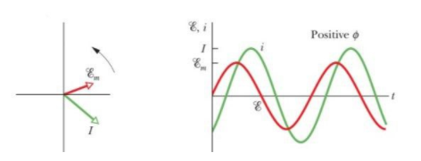
In the figure Em = max emf of the applied source.
If XC>XL then the circuit is said to be more capacitive than inductive. So the phase tanϕ is negative and that means the applied emf will lag behind the current. i.e.
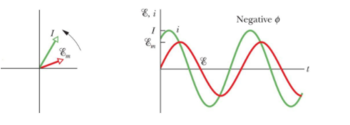
In the figure Em= max emf of the applied source.
If XC=XL which is the resonant condition the circuit will resist and in the resistive circuit the current and supplied emf is in the same phase.
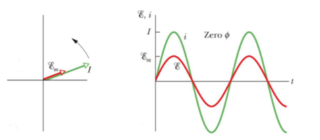
In the figure Em= max emf of the applied source.