Question
Question: A series LCR circuit is connected to an ac source. Using the phasor diagram, derive the expression f...
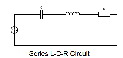
A series LCR circuit is connected to an ac source. Using the phasor diagram, derive the expression for the impedance of the circuit. Plot a graph to show the variation of current with frequency of the source, explaining the nature of its variation.
Solution
Draw the phasor diagram from the sense of the voltages across the each component in the circuit and use Pythagoras theorem to find the impedance of the circuit.
Complete answer:
We know that the voltage drop across a resistance is VR=IR where, I is the current in the circuit and R is the resistance of the circuit. The voltage across a inductor coil is, VL=IXL where XL=jωL is the inductive impedance, L is the inductance of the coil, ω is the frequency of the AC source.
The voltage drop across a capacitor is VC=IXC where , XC=jωC1 is the capacitive impedance, C is the capacitance of the capacitor.
Now, for a series LCR circuit, we can observe the voltage drops across each component as by the equations given above.
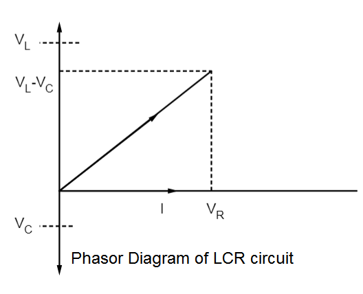
Now, we have to plot the phasor diagram. We can see that the voltage across L is a pure imaginary type quantity so it will be leading current I by 90∘ (is on the positive Y axis). The voltage across C is also a pure imaginary type quantity, hence it will lag current by 90∘ ( since j1=−j ), so it will be on the negative Y axis of the phasor diagram, . Voltage across R is a real quantity hence it will be in phase with the current I . The net voltage drop across the circuit will be a complex quantity as VNET=VR+VC+VL
So,
=IR+IXC+IXL =IR+jI(ωL−ωC1)
So, the VNET will be on the positive complex XY plane. So, the phasor diagram of the circuit is given in the diagram.
Now, we want to find the impedance Z of the circuit.
If we use Pythagoras theorem from the diagram (or take modulus on the both sides of the expression of VNET ) we get,
VNET2=VR2+(VL−VC)2
Now, putting the values of VL , VC and VR in the phase or complex plane.
∴(IZ)2=(IR)2+(IωL−ωCI)2
Cancelling out I from both sides we get,
⇒(Z)2=(R)2+(ωL−ωC1)2
Hence taking square root of the equation we get the expression of impedance as,
⇒Z=(R)2+(ωL−ωC1)2
This is our required expression for impedance of the circuit.
Now, to observe the nature of the variation of current vs. frequency, we have to observe this expression of the impedance,
We can write, VNET as, VNET=I(R)2+(ωL−ωC1)2
Hence, current is given as, I=(R)2+(ωL−ωC1)2VNET
We can see the variation of current with frequency is shown in the graph, when VNET , R,L and C are constants.
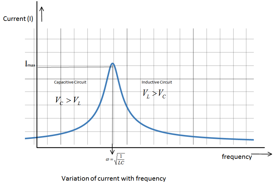
So, you can see, current will be maximum when the quantity (R)2+(ωL−ωC1)2 will be minimum.
This quantity will be minimum when , ωL=ωC1 , this is called the resonance condition. At resonance IMax=RVNET and resonance frequency is ω=LC1 .
For frequencies greater than resonant frequency, ω>LC1 ,
ωL>ωC1 ∴VL>VC
Hence, the circuit is inductive.
For, frequencies lesser than resonant frequency , ω<LC1
ωL<ωC1 ∴VC>VL
Hence, the circuit will be capacitive in this condition.
Note:
For a circuit with reactive elements, phase difference between current and voltage across the capacitor is always −90∘ or the voltage lags the current. Whereas, for an inductor phase difference between current and voltage across the inductor is always 90∘ or the voltage leads the current.