Question
Question: A series \[LCR\] circuit consists of an inductor \[L\] a capacitor \[C\] and a resistor \[R\] connec...
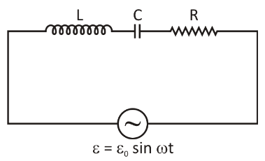
A series LCR circuit consists of an inductor L a capacitor C and a resistor R connected across a source of emf ε=ε0 sinωt. When ωL=ωC1 the current in the circuit is Io and if angular frequency of the source is changed to ω′, the current in the circuit becomes 2Io, then the value of ω′L=ω′C1 is
A. R
B. 3R
C. 15R
D. Zero
Solution
First of all, we will find the expression for the impedance. After that the expression of current, which involves resistance and impedance. We will put the as half the initial value to get another expression. We will manipulate these two expressions and try to obtain the result.
Formula used:
The impedance in the above circuit can be calculated by using the formula as below,
Let,Z=ωL−ωC1=0
and current is given by using the formula,
I0=R1+Z2ε0
Where,
I0 is the current.
ε0 is the e.m.f.
R is the resistance.
Z is the impedance.
Complete step by step solution:
So, at the resonance state we know that the impedance will be zero i.e,
Let,Z=ωL−ωC1=0
Then by formula we get, current Io
I0=R2+Z2ε0 …… (1)
If ω changes to ω′ we get,
Z′=ω′L−ω′C1
Then,I0=2I0
⇒2I0=R1+Z′ε0 …… (2)
From equation (1) and (2) we get,
⇒2R2+Z′=R2+Z′
∴Z′=3R
Since Impedance is zero at resonance so the correct answer is option B.
Note: It must be remembered that in an Ideal case of inductance and capacitance have an imaginary reactive impedance with respective to frequency. The impedance of inductance case increases as frequency is increased. However, it is important to note that the impedance of capacitance decreases as frequency is increased. Depending on the character of the reactance element of the impedance (whether inductance or capacitance) the alternating current both the lags or the leads of the voltage.