Question
Question: A rectangular frame ABCD made of a uniform metal wire has a straight connection between E and F made...
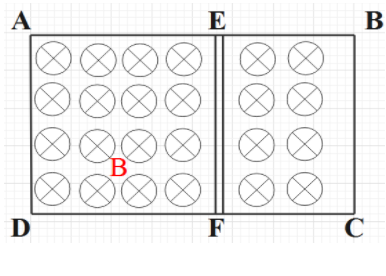
A rectangular frame ABCD made of a uniform metal wire has a straight connection between E and F made of the same wire as shown in figure. AEFD is a square of side 1m and EB=FC=0.5m. The entire circuit is placed in a steadily increasing, uniform magnetic field directed into the plane of paper and normal to it. The rate of change of the magnetic field is 1 T/s, The resistance per unit length of the wire is 1 Ω/m. Find the magnitude and direction of the current in the segment AE, BE and EF.
A)226A, E to A; 227A, B to E; 221A, F to EB)221A, E to A; 226A, B to E; 227A, F to EC)227A, E to A; 226A, B to E; 221A, F to ED)Zero, Zero, Zero
Solution
To solve this question, initially we need to find the induced emf due to change in magnetic field, using faraday’s law. Then, we need to draw an analogous circuit from the induced emf and the given resistance per unit length. By applying Kirchhoff’s law to each loops ADFEA and FCBEF, and solving the equations formed, we can find the current.
Formula used:
!!′!! s Voltage Law e=AdtdBKirchhoff
Complete step by step answer:
From the question, it is given that a metal wire ABCD, with a straight wire EF of the same material. This system is subjected to a magnetic field 1 T/s. From Faraday’s law of induction, when a closed circular loop is subjected to change in flux, emf is induced. The emf induced is given by,
e=dtdϕ
Where, e is the emf and ϕ is the magnetic flux.
e=dtdϕ=dtd(BA)=Adtd(B)⇒eAEFD=1m2×1Ωm−1=1V⇒eEBCF=0.5m2×1Ωm−1=0.5V
From this formula, we can find the emf induced in each loop. We can use Fleming’s left-hand rule to find the direction of current and here it will be in clockwise direction.
Now, it is mentioned that the wire has the resistance per unit length as 1 Ω/m. From the given data and the emf obtained, we can resolve the given rectangular frame into an equivalent electric circuit as follows.
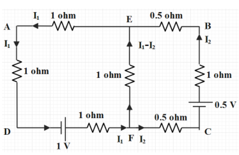
Now, to find the current, we will apply KVL in each loop. So,
Applying KVL in loop ADFEA, we will get,
−I1(1Ω)+1V−I1(1Ω)−(I1−I2)(1Ω)−I1(1Ω)=0⇒I1(4Ω)−I2(1Ω)=1V — eqn (1)
Then, Applying KVL in loop FCBEF, we will get,
−I2(0.5Ω)+0.5V−I2(1Ω)−I2(0.5Ω)+(I1−I2)(1Ω)=0⇒I2(3Ω)−I1(1Ω)=−0.5V — eqn (2)
Now, solving eqn (1) and eqn (2), we will get,