Question
Question: A part of a circuit in steady-state with current flowing in the branches with the value of each resi...
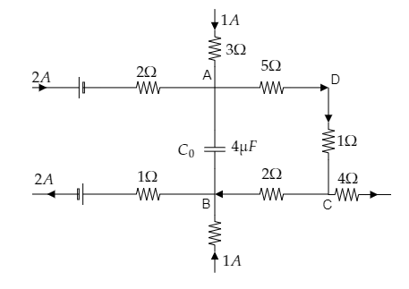
A part of a circuit in steady-state with current flowing in the branches with the value of each resistance is shown in the figure. Calculate the energy stored in the capacitor C0.
Solution
The energy stored in the capacitor will be proportional to the capacitance of that capacitor and the square of the potential difference across that capacitor. Now the potential difference across the capacitor can be obtained by Ohm’s law and Kirchoff’s junction rule. Kirchoff’s junction rule gives the current entering or leaving a junction as the sum of the currents through the branches of that junction.
Formulae used:
Ohm’s law gives the potential difference between two points in a circuit as V1−V2=IR where I is the current through the resistor connected across the two points and R is the resistance of that resistor.
Kirchoff’s junction rule is given by, I=i1+i2 where I is the current entering or leaving a junction, i1 and i2 are the currents through two branches of the junction.
The energy stored in a capacitor is given by, U=21CV2 where C is the capacitance of the capacitor and V is the potential difference across the capacitor.
Complete step by step answer:
Step 1: Sketch the given figure and mark the junctions of interest.
From the above figure, we have to determine the potential difference VA−VB across the capacitor C0 using Ohm’s law and Kirchoff’s junction rule.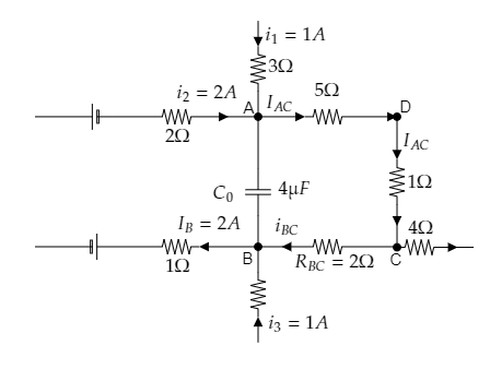
Step 2: Make use of Kirchoff’s junction rule and Ohm’s law to obtain the potential difference across the capacitor.
The effective resistance of the 5Ω and 1Ω resistances connected across the points A and C will be RAC=5+1=6Ω .
Also from the figure, we see that the currents i1=1A and i2=2A through the branches of junction A combine to a total of IAC=i1+i2⇒IAC=3A. This current flows through the effective resistance RAC .
So the potential difference across the two points A and C will be given by Ohm’s law as VA−VC=IACRAC=3×6=18V -------- (1)
Now at junction B, the currents through its two branches iBC and i3=1A combine to a total current of IB=2A .
So by Kirchoff’s junction rule, we have IB=iBC+i3⇒iBC=IB−i3 .
Then we obtain the current through the resistance RBC=2Ω as iBC=2−1=3A .
Then the potential difference between the points C and B will be
VC−VB=iBCRBC=1×2=2V ------- (2)
Adding equations (1) and (2) we obtain VA−VC+VC−VB=18 + 2=20V
⇒VA−VB=20V
Thus the potential difference across the capacitor is obtained to be VA−VB=20V .
Step 3: Express the relation for the energy stored in the capacitor C0=4μF .
The energy stored in the capacitor C0 can be expressed as U=21C0(VA−VB)2 -------- (3)
Substituting for C0=4×10⁻⁶F and VA−VB=20V in equation (3) we get, U=21×4×10−6×202=8×10⁻⁴J
∴ The energy stored in the given capacitor is obtained to be U=8×10⁻⁴J.
Note: In the sketched figure, the 5Ω and 1Ω resistances connected across the points A and C are connected serially. So the effective resistance RAC of these two resistors is taken to be the sum of their sum. While substituting values of quantities in an equation, make sure that all the quantities are expressed in their respective S.I units. Here the capacitance of the given capacitor was expressed in the units of micro-farads. So we made the conversion into the S.I unit of farads as C0=4×10⁻⁶F before substituting in equation (3).