Question
Question: A flashlight cell of emf \(1 \cdot 5{\text{volts}}\) gives \(15{\text{A}}\) current when connected t...
A flashlight cell of emf 1⋅5volts gives 15A current when connected to an ammeter of resistance 0⋅04Ω. Find the internal resistance of the cell.
A) 0⋅04Ω
B) 0⋅06Ω
C) 0⋅10Ω
D) 10Ω
Solution
Here the cell is connected directly to an ammeter. So the internal resistance of the flashlight cell and that of the ammeter will form a series connection. Ohm’s law gives the effective resistance of the circuit to be directly proportional to the voltage and inversely proportional to the current in the circuit.
Formulas used:
-The effective resistance of two resistors in series is given by, Reff=R+r where R and r are the resistances of two resistors in series.
-The effective resistance of a circuit as per Ohm’s law is given by, Reff=IV where V is the voltage across the circuit and I is the current in the circuit.
Complete step by step answer.
Step 1: Sketch a circuit diagram depicting the above mentioned setup and list the parameters provided in the question.
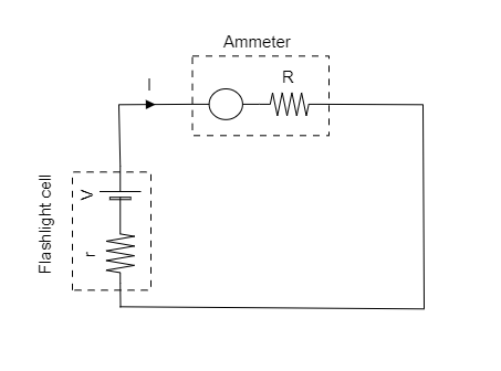
The emf or voltage of the cell is given to be V=1⋅5V .
The current in the circuit is given to be I=15A .
The resistance of the ammeter is given to be R=0⋅04Ω .
Step 2: Express the effective resistance of the circuit.
As the internal resistance r of the cell and the resistance of the ammeter are connected in series, the effective resistance of the circuit can be expressed as Reff=R+r ------- (1)
Substituting for R=0⋅04Ω in equation (1) we get, Reff=0⋅04+r .
Thus the effective resistance of the circuit is Reff=0⋅04+r .
Step 3: Based on Ohm’s law, express the effective resistance of the given circuit.
According to Ohm’s law, the effective resistance of the given circuit can be expressed as
Reff=IV ----------- (2)
Substituting for Reff=0⋅04+r, V=1⋅5V and I=15A in equation (2) we get, 0⋅04+r=151⋅5
⇒r=0⋅1−0⋅04=0⋅06Ω .
Thus the internal resistance of the flashlight cell is r=0⋅06Ω .
So the correct option is B.
Note: An ammeter is always connected in series with the device of whose current is to be recorded. Here the current through the flashlight cell is given and so the ammeter is connected in series with the cell. A series connection of resistors is obtained when one of the ends of each resistor are connected together. In our sketched circuit diagram, we see that only one end of both resistors R and r are connected together.