Question
Question: (A)Draw a circuit diagram of transistor as an amplifier in common emitter configuration. (B) Obtai...
(A)Draw a circuit diagram of transistor as an amplifier in common emitter configuration.
(B) Obtain the expression for the voltage gain.
Solution
Hint: First of all, we will draw the circuit diagram and then using that circuit diagram we will find the input and output voltage. Now, the ratio of output voltage and input voltage Is voltage gained which can be expressed mathematically as, Av=input voltageoutput voltage. Using this expression, we will find the solution.
Formula used: Av=input voltageoutput voltage
Complete step by step answer:
Before drawing the circuit diagram we will understand what transistors are, so, a transistor is a semiconductor device which is used to amplify or switch electronic signals and electrical power. It is made up of semiconductor material and it usually has at least three terminals i.e. Base, Collector and Emitter, for connection to an external circuit.
Now, in the question we are asked to draw the circuit diagram of a transistor as an amplifier in common emitter common configuration, which is shown in the figure below,
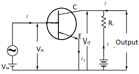
Where, IB is base current, IE is emitter current, IC is collector current, VBE is voltage difference between base and emitter, VCE is voltage difference between collector and emitter VBB is base power supply and VCC is collector power supply.
Now, from the circuit diagram it can be seen that the input voltage is VBE. Now, we know that V=IR,
Where, I is current and R is resistance, so, applying the same in VBE we will get,
VBE=IBRin …………………(i)
Now, same way the output voltage is VCE and it can be written as,
VCE=ICRout ………………..(ii)
Now, the voltage gain is given by,
Av=input voltageoutput voltage
So, now substituting the values of input and output voltages in above equation we will get,
Av=input voltageoutput voltage
Av=VBEVCE=(IB)Rin(IC)Rout …………………….(iii)
Now, IBIC is called current gain which can be given as βAC, so substituting it in expression (iii) we will get,
Av=βACRinRout.
Thus, voltage gain can be given by, Av=βACRinRout.
Note: Students might make mistake in considering the input and output voltage as VBE and VCE, instead of that they might consider the VBB and VCC as input and output voltages and due to that the answer will be wrong. So, students must take care while solving such problems.