Question
Question: A conducting circular loop of copper is placed as shown in figure. Cross section area of part abc is...
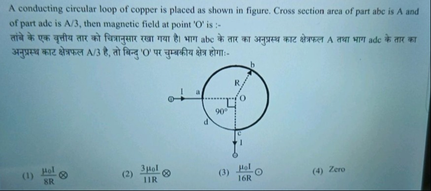
A conducting circular loop of copper is placed as shown in figure. Cross section area of part abc is A and of part adc is A/3, then magnetic field at point 'O' is :-
तांबे के एक वृत्तीय तार को चित्रानुसार रखा गया है। भाग abc के तार का अनुप्रस्थ काट क्षेत्रफल A तथा भाग adc के तार का अनुप्रस्थ काट क्षेत्रफल A/3 है, तो बिन्दु 'O' पर चुम्बकीय क्षेत्र होगाः-
8Rμ0I⨂
11R3μ0I⨂
16Rμ0I⨀
Zero
8Rμ0I⨂
Solution
We shall show that even though the same “supply‐current” I is fed between the two contact points a and c, the “circular” part is actually made of two branches (from a to c) of different “resistive” weights so that the “circulating” current (that which produces a field at the centre) is given by the difference between the currents in the two arcs. One very plausible assumption (consistent with the figure) is to take the two arcs joining a and c so that one (the “abc–part”) subtends 270° and has uniform cross–section A (“thick”) while the other (the “adc–part”) subtends 90° and has area A/3 (“thin”). (In a copper wire, resistance ∝ length/area.) Then
-
The resistances are
R₍abc₎ = (ρ·(3πR/2))/A and R₍adc₎ = (ρ·(πR/2))/(A/3) = (3ρπR)/(2A).
Thus, R₍abc₎ = R₍adc₎. Hence the potential difference (set by the external connecting wires of negligibly small resistance) makes the currents in the two arms equal:
I₍abc₎ = I₍adc₎ = I/2.
Now note that although both currents (of magnitude I/2) run from a to c along the two separate wires, when they “rejoin” to form the closed circular loop the parts of the loop are traversed in opposite senses. (That is, if on the major arc you follow the “natural” direction from a to c then to complete the loop the actual current there is opposite to the “given” sense.) In other words, when we “close the loop” the magnetic field contributions add with opposite signs. For a circular arc of radius R carrying current I′ and subtending an angle θ (in radians), the field at the centre is
B = (μ₀I′ θ)/(4πR).
Thus, if we choose a “sign‐convention” (say “counter–clockwise” as positive) then we may assign:
-
to the “abc–arm” (270° = 3π/2) the contribution
B₁ = (μ₀(I/2)(3π/2))/(4πR) = (3μ₀I)/(16R),
-
to the “adc–arm” (90° = π/2) the contribution (but note that to have a closed loop the actual current there runs opposite to the above sign)
B₂ = – (μ₀(I/2)(π/2))/(4πR) = – (μ₀I)/(16R).
Thus the net field is
B_net = B₁ + B₂ = (3μ₀I)/(16R) – (μ₀I)/(16R) = (2μ₀I)/(16R) = μ₀I/(8R).
The direction (indicated by the symbol ⊗) comes following the right–hand rule for the net “circulating” current.