Question
Question: A common emitter amplifier circuit built using an n-p-n transistor is shown in the figure. Its DC cu...
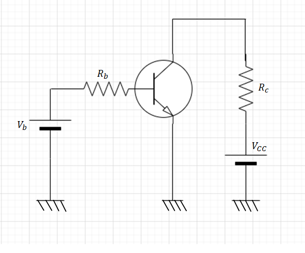
A common emitter amplifier circuit built using an n-p-n transistor is shown in the figure. Its DC current gain is 250 RC=1kΩ and Vcc=10V. What is the minimum base current for VCE to reach saturation is:
a. 100μA
b. 7μA
c. 40μA
d. 10μA
Solution
The n-p-n transistor is the transistor which is used to when we need to sink the current .Current gain is ratio between collector current and base current so first calculate collector current then use current gain equation to calculate the base current.
Formula used:
The formula for the collector current is given by,
⇒iC=RCVCC
Where the collector current is iC the resistance is RC and the voltage is VCC.
Complete step by step answer:
Step1:
At the saturation point the voltage VCE becomes zero.
Given that VCC=10V
Therefore current in the collector is given by-
⇒iC=RCVCC
The value of VCC=10V.
⇒iC=100010
⇒iC=10mA
Step2:
Now use the current gain equation to calculate the base current.
⇒β=iBiC
Where β= current gain =250
Put values in above equation we get,
⇒250=iB10
⇒iB=25010mA
⇒iB=40μA
The required current in the base is equal to iB=40μA.
Hence, the correct answer is option (C).
Additional information:
The configuration in which the emitter is connected between the collector and base is known as a common emitter configuration. The input circuit is connected between emitter and base, and the output circuit is taken from the collector and emitter. Thus, the emitter is common to both the input and the output circuit, and hence the name is the common emitter configuration.
Note: The saturation region allows the transistor to conduct current from the emitter to the collector. With both the base collector junction and the base emitter junction forward-biased, the base current is so strong it exceeds the magnitude at which it can increase the collector current flow. Always keep in mind that at the saturation point VCE becomes zero.