Question
Question: A capacitor circuit consists of two \(6\mu F\) and \(3\mu F\) capacitors is initially charged to 100...
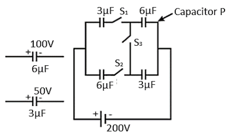
A capacitor circuit consists of two 6μF and 3μF capacitors is initially charged to 100V and 50V respectively now connected to a source of EMF 200 volt through the switches S1,S2 and S3 as shown in the figure below. Charge on capacitor P, in steady state, when S1 is closed.
Solution
Hint: We first need to know how the circuit looks when the switch S1 is closed. Then we’ll find out the equivalent capacitance of the circuit using the formula C1=C11+C21, where charge can be found using the formula, q=CV. Therefore, the final result can be easily found out.
Formula used:
C1=C11+C21
Complete step-by-step solution:
It is said that the capacitors are initially charged.
Let C1=3μF and C2=6μF.
It is given in the question that the initial voltage across the first capacitor is C1 is 50V. And the initial voltage across the second capacitor C2 is 100V.
So, the charge of first capacitor C1 is,
q1=C1.V1=3μ×50=150μ Coulomb
Similarly, the charge across the second capacitor is given by,
q2=C2.V2=6μ×100=600μ Coulomb
But when the circuit is connected to the 200 volt source, the charges are redistributed in a new way.
In order to find this new charge, we need to find the equivalent capacitance of the circuit. Imagine only S1 is closed and all the other keys are opened. So, the two capacitors are in series connections. Equivalent capacitance is given by,
C1=C11+C21
After putting the values in the formula, we obtain,
C1=3μ1+6μ1⇒C1=6μ2+1⇒C1=6μ3
∴C=2μF
The voltage across this new equivalent capacitor is 200V. Now the charge along the equivalent capacitor is given by,
q=CV=2μ×200=400μ Coulomb
In series connection of capacitors, all the capacitors possess the same amount of charge. So, the charge across the capacitor P is 400μ or 0.004 Coulomb.
Additional information:
When two or more capacitors are connected in parallel connection, their equivalent capacitance is given by the sum of the individual capacitances, i.e., C=C1+C2+....
Note: Don’t get bothered about the initial charges of the capacitors. Since it is mentioned in the question that we have to find the charge on “steady state”, we only need to consider the final conditions of the circuit. In case of parallel connection, the charge on each individual capacitor is not the same.
The problem occurs when the circuit is considered as having parallel capacitor connections rather than series capacitor connections, the answer will not be the same.