Question
Question: A capacitance of \(\left( \dfrac{{{10}^{-3}}}{2\pi } \right)F\) and an inductance of \(\left[ \dfrac...
A capacitance of (2π10−3)F and an inductance of [π100]mH and a resistance of 10Ω are connected in series with an AC voltage source of 220V, 50 Hz. The phase angle of the circuit is
A. 600B. 300C. 450D. 900
Solution
To solve this question, obtain the information regarding the phase of different electrical components. The phase of the capacitor is ninety degrees behind the phase of the current flow and the phase of the inductor is ninety degrees before the current. The phase of the resistance and the current is the same. Obtain the required mathematical expression to find the phase angle and then put the given values to find the required answer.
Complete answer:
The capacitor, inductor and the resistance are connected in series with an AC source.
Given, the capacitance is (2π10−3)F and the inductance is [π100]mH and the resistance is 10Ω
The voltage of the AC source is 220V and the frequency is f=50Hz
We need to find the phase angle of the circuit. Let us draw the phasor diagram for the circuit.
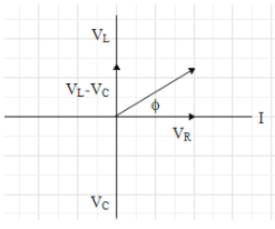
Let, the current through the circuit is in the positive x direction.
Now, we can say that the phase of the voltage through the inductor will be 2π above in the anticlockwise direction. The phase of the voltage through the capacitor will be 2π behind in the clockwise direction. The phase of the voltage through the resistance will be in the same direction as the current through the circuit.
The angle between the phases of the resultant of the VL,Vc,VR and the phase of the current is called the phase angle of the circuit.
Mathematically, the phase angle can be expressed as,
tanϕ=VRVL−VC=IRIXL−IXCtanϕ=RXL−XC
Now, the XL and XCcan be expressed in terms of the frequency of the AC source as,
XL=ωL=2πfLXL=2π50π100×10−3XL=10
And
XC=ωC1=2πfC1XC=2π502π10−31XC=20
Now, putting the obtained values in the equation for the phase angle,
tanϕ=RXL−XCtanϕ=10∣10−20∣tanϕ=1ϕ=tan−11ϕ=450
So, the phase angle of the circuit is 450.
The correct option is (C).
Note:
The notation XC is used in the above equations is the capacitive reactance and the notation XL is the inductive reactance. The reactance can be defined as the opposition offered by the capacitor and the inductor to the flow of the AC current through the circuit.