Question
Question: \[A\], \[B\], \(C\), \[D\], \[E\] and \[F\] are conducting plates each of area \[A\] and any two con...
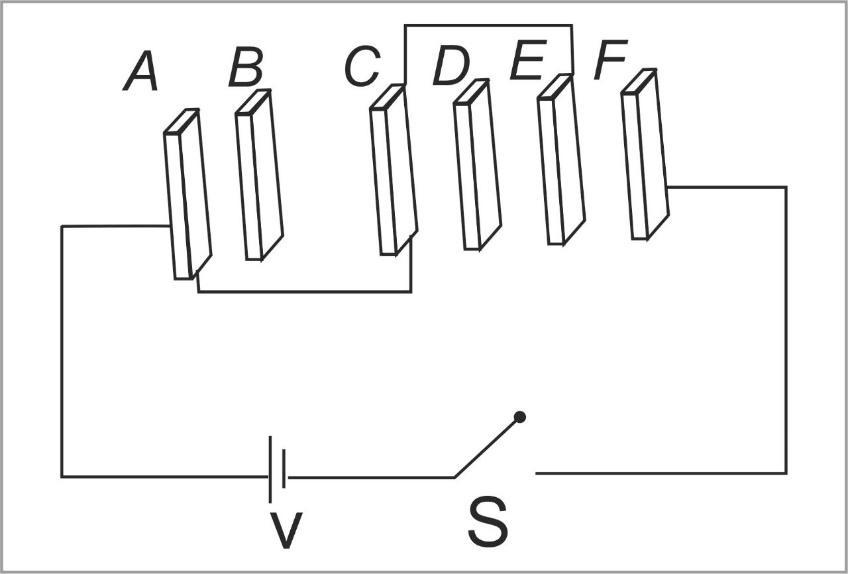
A, B, C, D, E and F are conducting plates each of area A and any two consecutive plates are separated by a distance d as shown in the given figure. The energy in system after the switch S is closed is-
A) 2d3ε0AV2
B) 12d5ε0AV2
C) 2dε0AV2
D) dε0AV2
Solution
Simplify the given figure in an easier circuit, where all the connections are clear, and the capacitors are placed accordingly. Then seeing the series and parallel conditions of the capacitors, the question can be solved. Also after simplifying the circuit one can see that most capacitors are short circuited(potential drop across them is zero hence charge on them will be zero)
Complete step by step answer:
In this question, we have given a combination of two plates, which forms a capacitor (a passive electronic component with two terminals) with a distance of ‘d’ units in between the plates. Now we know that the formula for capacitance of one capacitor is given as-
⇒C=dε0A
So, in order to find energy in the system we can apply the formula,
U=2CeqV2......(1)
Where, Ceq is the equivalent capacitance of the entire circuit.
A is the plate area
V is the voltage across the circuit
Now simplifying the given figure, we get,
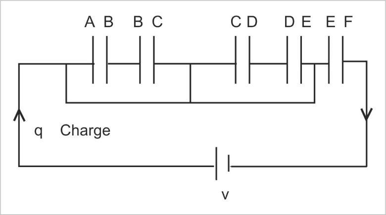
Now we can clearly say that the charge will flow through the conducting wires below the capacitors because it has no kind of hindrance and this will be till the charge q reaches the last capacitor only at that capacitor it will be stored. So, the middle capacitors are practically of no use. More technically we can say that The plates A and C are connected among themselves, hence the potential difference between the plates will be zero. Similar is the case for plates C and E. Hence the potential difference between plates C and E is also zero.
Therefore, no charge flows if there is no potential difference.
Therefore, the equivalent capacitance will be,
⇒Ced=dε0A
Now we substitute the value of the equivalent capacitance in equation (1) as,
∴U=2dε0AV2
Thus, the correct option is (C).
Note: Always remember that charge flows from high potential area to low potential area and will always choose an easier and obstacle free path to travel in a circuit. And we are careful about the capacitor that is which one is in use or which is not in use in the circuit.