Question
Question: A, B and C are the voltmeters of resistance 1R, 1.5R and 3R respectively as shown in the figure. Whe...
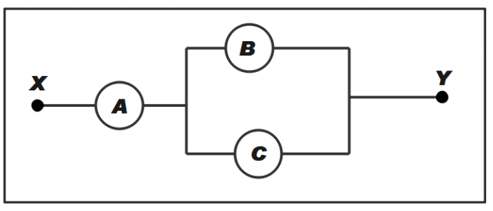
A, B and C are the voltmeters of resistance 1R, 1.5R and 3R respectively as shown in the figure. When some potential difference is applied between X and Y, the voltmeter reading are VA, VB and VC respectively. Then
A. VA=VB=VC
B. VA=VB=VC
C. VA=VB=VC
D. VA=VB=VC
Solution
In this question we are being asked the relation between VA,VBand VC. As we can see from the figure the resistor B and C are parallel. Therefore, we will have to calculate the equivalent resistance. The circuit is said to be given some potential difference. After calculating the equivalent resistance we can state the relation by using the Ohm’s law.
Formula used:
V = IR
Where V is the potential difference, R is the resistance and I is the current flowing through the circuit.
Complete step-by-step answer:
We have been given that resistance in A is R and that in B and C is 1.5R and 3R respectively. From the diagram we can see that resistance B is parallel to C. Therefore,
We know, the equivalent resistance for resistors in parallel combination is given by,
Req1=R11+R21
Where,
Req = the equivalent resistance
R1 = resistance in B
R2 = resistance in C
Therefore, after substituting values in above equation we get,
Req1=1.5R1+3R1
On solving above equation
We get,
Req1=3R3
Therefore,
Req=R………….. (1)
Now we know from ohm’s law
V = IR
Here we shall assume that current is the same throughout the circuit.
Therefore, we can say that potential difference is directly proportional to resistance.
V∝R
From (1) we can say that equivalent resistance of B and C is R which is also the resistance for A. It means that resistance in every branch is equal to A.
Therefore, we can say that potential difference is same across A, B and C i.e. VA=VB=VC.
So, the correct answer is “Option C”.
Note: A voltmeter is the electric device that is used to measure the potential difference across two points in an electric circuit. Voltmeters show the deflection through the needle. They also show the direction of voltage applied. The voltmeter is always connected in parallel with the points between which the potential difference is to be measured.