Question
Question: (a) An ac circuit as shown in the figure has an inductor of inductance \[L\] and a resistor of resis...
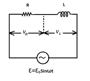
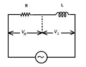
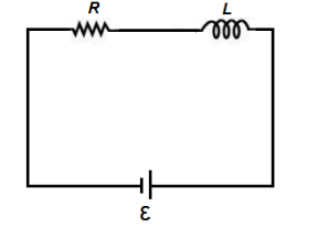
(a) An ac circuit as shown in the figure has an inductor of inductance L and a resistor of resistance connected in series. Using the phasor diagram, explain why the voltage in the circuit will lead the current in phase.
(b)The potential difference across the resistor is 160V and that across the inductor is 120V. Find the effective value of the applied voltage. If the effective current in the circuit be 1.0A. Calculate the total impedance of the circuit.
(c) What will be the potential difference in the circuit when direct current is passed through the circuit?
Solution
First of all, we will draw the diagrams for which the solution will be easy to proceed. After that for the impedance part, we will individually find out resistance and the impedance. To calculate the effective value of the added voltage, we will use both the voltages of resistor and the inductor.
Complete step by step answer:
In the given question, we are supplied with the following data:
The figure has an inductor of inductance L and a resistor of resistance connected in series.
(a) We are asked to find out why the voltage in the circuit will lead the current in phase.
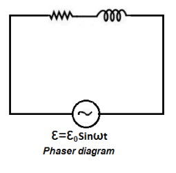
ε is ϕ ahead of i . For better understanding we draw the following diagrams:
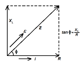
This is due to the fact that i and R are in phase and i.e., Z and ε are in phase as ε=ε0sinωt from diagram
i=Zε0sin(ωt−ϕ)
Where, ϕ=tan−1RXL
(b) We are given that the current is 1A .
i=1.0A (Given)
Potential difference across the inductor is given as VL=120V.
We know from the Ohm’s law,
VL=iXL …… (1)
Where,
VL indicates the voltage across the inductor.
i indicates the current flowing through it.
XL indicates the inductive reactance.
Now by substituting the required values in the equation (1), we get:
Potential difference across the resistor is VR=160V .
We know,
VR=iR …… (2)
Where,
VR indicates the voltage across the resistor.
i indicates the current flowing through it.
R indicates the resistance of the resistor.
{V_R} = iR \\\
\Rightarrow 160 = 1 \times R \\\
\Rightarrow R = \dfrac{{160}}{1} \\\
\Rightarrow R = 160\,{\Omega } \\\
\Rightarrow{V_{net}} = \sqrt {{V_R}^2 + {V_L}^2} \\\
\Rightarrow{V_{net}} = \sqrt {{{\left( {160} \right)}^2} + {{\left( {120} \right)}^2}} \\\
\Rightarrow{V_{net}} = \sqrt {25600 + 14400} \\\
\therefore{V_{net}} = 200\,{\text{V}} \\\
Hence, the effective value of applied voltage is 200V .
Now, we will find the net impedance, which is given by the following manipulation:
Z = \sqrt {{R^2} + {X_L}^2} \\\
\Rightarrow Z = \sqrt {{{\left( {160} \right)}^2} + {{\left( {120} \right)}^2}} \\\
\therefore Z = 200\,{\Omega} \\\
Hence, the total impedance of the circuit is 200Ω .
(c) When direct current is passed through the circuit then R will be zero at t=ω, inductor will act as plane wire and potential drop will only act occur at R
(i=Rε)
For intermediate time, we can write:
E=iR+dtLdi
In this case, current i will vary accordingly.
Note: This problem can be solved if you have a sound knowledge about phasor diagrams and alternating current. It should be remembered that in a purely capacitive circuit, the current will lead the voltage. Impedance is the net effective resistance offered by an electric circuit which contains resistor and inductor.