Question
Question: 8) With an example state and explain KVL. 10. In the circuit shown in Figure determine all branch c...
- With an example state and explain KVL.
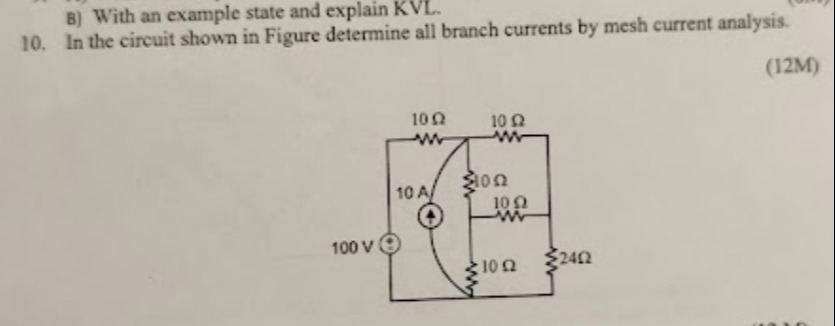
- In the circuit shown in Figure determine all branch currents by mesh current analysis.
Part 1: KVL
- Statement: The algebraic sum of voltages around any closed loop in a circuit is zero.
- Explanation: Consequence of energy conservation; voltage rises balance voltage drops.
- Example: For a series circuit with source Vs and resistors R1, R2, KVL states Vs = IR1 + IR2.
Part 2: Mesh Current Analysis
Mesh Currents:
- I1 = -8/3 A
- I2 = 22/3 A
- I3 = 20/9 A
Branch Currents:
- Current through 100V source: 8/3 A (downwards)
- Current through top-left 10Ω resistor: 8/3 A (right to left)
- Current through 10A current source: 10 A (upwards)
- Current through top-right 10Ω resistor: 22/3 A (left to right)
- Current through middle-vertical 10Ω resistor: 46/9 A (downwards)
- Current through middle-horizontal 10Ω resistor: 46/9 A (right to left)
- Current through bottom-left 10Ω resistor: 44/9 A (right to left)
- Current through right-vertical 24Ω resistor: 20/9 A (downwards)
Solution
The problem consists of two parts:
- State and explain Kirchhoff's Voltage Law (KVL) with an example.
- Determine all branch currents in the given circuit using mesh current analysis.
Part 1: Kirchhoff's Voltage Law (KVL)
Statement: Kirchhoff's Voltage Law states that the algebraic sum of all voltages (potential differences) around any closed loop or path in an electrical circuit is equal to zero. This law is a direct consequence of the principle of conservation of energy.
Explanation: As one traverses a closed loop in a circuit, any increase in electric potential (voltage rise, e.g., across a battery from negative to positive terminal) must be balanced by an equal decrease in electric potential (voltage drop, e.g., across a resistor in the direction of current flow) such that the net change in potential is zero when returning to the starting point. Mathematically, for a closed loop: ∑V=0 where ∑V is the algebraic sum of voltages around the loop.
Example: Consider a simple series circuit consisting of a voltage source Vs and two resistors R1 and R2. Let the current flowing through the circuit be I.
Assuming the current I flows clockwise from the positive terminal of Vs through R1 and R2 back to the negative terminal. The voltage drop across R1 is V1=IR1. The voltage drop across R2 is V2=IR2.
Applying KVL around the loop (starting from point A, moving clockwise): We encounter a voltage rise across the source Vs (from negative to positive). We encounter voltage drops across resistors R1 and R2 (in the direction of current).
−Vs+V1+V2=0 Vs=V1+V2 Substituting the voltage drops in terms of current and resistance using Ohm's Law: Vs=IR1+IR2 Vs=I(R1+R2) This equation shows that the total voltage supplied by the source is equal to the sum of voltage drops across the resistors, illustrating the conservation of energy within the closed loop.
Part 2: Mesh Current Analysis
Circuit Diagram and Mesh Current Assignment:
Let's label the mesh currents I1, I2, and I3 in a clockwise direction as shown below:
- Let I1 be the clockwise mesh current in the leftmost mesh.
- Let I2 be the clockwise mesh current in the top-right mesh.
- Let I3 be the clockwise mesh current in the bottom-right mesh.
1. Current Source Constraint (Supermesh Equation): The 10A current source is shared between Mesh 1 and Mesh 2. The source direction is upwards. In Mesh 2, I2 flows upwards through the current source. In Mesh 1, I1 flows downwards through the current source. Thus, the current flowing upwards through the source is I2−I1. I2−I1=10(Equation 1)
2. KVL for the Supermesh (Mesh 1 + Mesh 2): Apply KVL around the outer boundary of Mesh 1 and Mesh 2, excluding the branch with the current source. Starting from the bottom-left corner (negative terminal of 100V source) and moving clockwise: Elements in the supermesh path: 100V source, top-left 10Ω resistor, top-right 10Ω resistor, middle-vertical 10Ω resistor, middle-horizontal 10Ω resistor, bottom-left 10Ω resistor.
−100+(I1×10)+(I2×10)+(I2−I3)×10+(I2−I3)×10+(I1−I3)×10=0 −100+10I1+10I2+10I2−10I3+10I2−10I3+10I1−10I3=0 Combine terms: 20I1+30I2−30I3=100 Divide by 10: 2I1+3I2−3I3=10(Equation 2)
3. KVL for Mesh 3: Apply KVL to Mesh 3. Starting from the top-left corner of Mesh 3 (junction of middle-vertical 10Ω, middle-horizontal 10Ω, and bottom-left 10Ω) and moving clockwise: (I3−I2)×10+(I3−I2)×10+(I3×24)+(I3−I1)×10=0 10I3−10I2+10I3−10I2+24I3+10I3−10I1=0 Combine terms: −10I1−20I2+(10+10+24+10)I3=0 −10I1−20I2+54I3=0 Divide by 2: −5I1−10I2+27I3=0(Equation 3)
4. Solving the System of Equations:
We have three equations:
- I2−I1=10⟹I2=I1+10
- 2I1+3I2−3I3=10
- −5I1−10I2+27I3=0
Substitute Equation 1 into Equation 2: 2I1+3(I1+10)−3I3=10 2I1+3I1+30−3I3=10 5I1−3I3=−20(Equation 4)
Substitute Equation 1 into Equation 3: −5I1−10(I1+10)+27I3=0 −5I1−10I1−100+27I3=0 −15I1+27I3=100(Equation 5)
Now we have a system of two equations with two variables: 4. 5I1−3I3=−20 5. −15I1+27I3=100
Multiply Equation 4 by 3: 15I1−9I3=−60(Equation 4’)
Add Equation 4' and Equation 5: (15I1−9I3)+(−15I1+27I3)=−60+100 18I3=40 I3=1840=920 A
Substitute I3=920 A into Equation 4: 5I1−3(920)=−20 5I1−320=−20 5I1=−20+320=3−60+20=3−40 I1=15−40=−38 A
Substitute I1=−38 A into Equation 1: I2=I1+10=−38+10=3−8+30=322 A
Mesh Currents:
- I1=−38 A (or ≈−2.67 A)
- I2=322 A (or ≈7.33 A)
- I3=920 A (or ≈2.22 A)
5. Determine all Branch Currents:
- Current through 100V source (IV1): This is I1. Since I1 is negative, it means the current flows counter-clockwise in Mesh 1. So, IV1=38 A flowing downwards (from positive to negative terminal).
- Current through top-left 10Ω resistor (IR1_top_left): This is I1. So, IR1_top_left=−38 A (left to right), meaning 38 A flows from right to left.
- Current through 10A current source (ICS): This is I2−I1=322−(−38)=322+8=330=10 A (upwards), consistent with the source value.
- Current through top-right 10Ω resistor (IR2_top_right): This is I2. So, IR2_top_right=322 A (left to right).
- Current through middle-vertical 10Ω resistor (IR3_mid_vert): This current is affected by I2 (downwards) and I3 (upwards). So, IR3_mid_vert=I2−I3=322−920=966−20=946 A (downwards).
- Current through middle-horizontal 10Ω resistor (IR4_mid_horiz): This current is affected by I2 (rightwards) and I3 (leftwards). So, IR4_mid_horiz=I2−I3=322−920=946 A (rightwards).
- Current through bottom-left 10Ω resistor (IR5_bottom_left): This current is affected by I1 (leftwards) and I3 (rightwards). So, IR5_bottom_left=I1−I3=−38−920=9−24−20=−944 A (leftwards), meaning 944 A flows from right to left.
- Current through right-vertical 24Ω resistor (IR6_right_vert): This is I3. So, IR6_right_vert=920 A (downwards).
Solution Summary:
Part 1: KVL
- Statement: The algebraic sum of voltages around any closed loop in a circuit is zero.
- Explanation: Consequence of energy conservation; voltage rises balance voltage drops.
- Example: For a series circuit with source Vs and resistors R1,R2, KVL states Vs=IR1+IR2.
Part 2: Mesh Current Analysis
Mesh Currents:
- I1=−38 A
- I2=322 A
- I3=920 A
Branch Currents:
- Current through 100V source: 38 A (downwards)
- Current through top-left 10Ω resistor: 38 A (right to left)
- Current through 10A current source: 10 A (upwards)
- Current through top-right 10Ω resistor: 322 A (left to right)
- Current through middle-vertical 10Ω resistor: 946 A (downwards)
- Current through middle-horizontal 10Ω resistor: 946 A (right to left)
- Current through bottom-left 10Ω resistor: 944 A (right to left)
- Current through right-vertical 24Ω resistor: 920 A (downwards)