Question
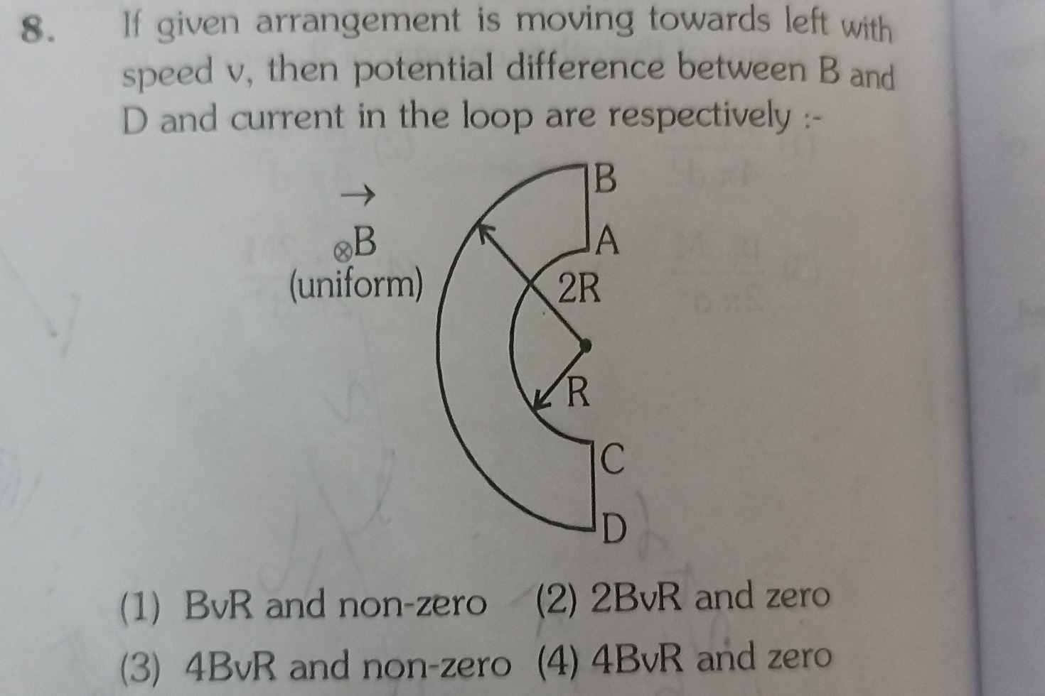
Question: If given arrangement is moving towards left with speed v, then potential difference between B and D ...
If given arrangement is moving towards left with speed v, then potential difference between B and D and current in the loop are respectively :-
BvR and non-zero
2BvR and zero
4BvR and non-zero
4BvR and zero
2BvR and zero
Solution
The problem describes a C-shaped conductor moving to the left with velocity v in a uniform magnetic field B directed into the page. We need to find the potential difference between points B and D, and the current in the loop.
Let's set up a coordinate system:
- Velocity of the arrangement: v=−vi^ (moving to the left).
- Magnetic field: B=−Bk^ (into the page).
The motional EMF induced across a conductor segment dl is dE=(v×B)⋅dl.
First, let's calculate the term (v×B): v×B=(−vi^)×(−Bk^)=vB(i^×k^)=vB(−j^).
So, the induced electric field (and the force on positive charges) is directed downwards, in the negative y-direction.
The potential difference VP2−VP1 across a segment from P1 to P2 is given by VP2−VP1=−∫P1P2(v×B)⋅dl.
Substituting (v×B)=−vBj^, we get: VP2−VP1=−∫P1P2(−vBj^)⋅dl=vB∫P1P2j^⋅dl.
This means that only the vertical component of the displacement contributes to the potential difference.
Let's analyze each segment of the loop:
-
Segment AB: This is a straight vertical conductor. From the diagram, B is above A. The length of this segment is the difference between the outer radius (2R) and inner radius (R), so LAB=2R−R=R. The displacement vector dl for going from A to B is in the positive y-direction (dyj^). VB−VA=vB∫ABj^⋅(dyj^)=vB∫ABdy=vBR. So, VB=VA+BvR. (B is at higher potential than A).
-
Segment CD: This is also a straight vertical conductor. From the diagram, C is above D. The length of this segment is LCD=2R−R=R. The displacement vector dl for going from D to C is in the positive y-direction (dyj^). VC−VD=vB∫DCj^⋅(dyj^)=vB∫DCdy=vBR. So, VC=VD+BvR. (C is at higher potential than D).
-
Arc AC (Inner Arc): This is a curved conductor. The diagram shows it as a horizontal arc connecting A and C. For any segment dl along this horizontal arc, dl is tangential and therefore horizontal. Since j^⋅dl=0 for a horizontal dl, the potential difference VC−VA=0. Therefore, VA=VC.
-
Arc DB (Outer Arc): This is also a curved conductor, shown as a horizontal arc connecting D and B. Similar to arc AC, for any segment dl along this horizontal arc, dl is horizontal. Thus, the potential difference VB−VD=0. Therefore, VB=VD.
Potential difference between B and D: From our calculation for Arc DB, we found VB−VD=0.
Current in the loop: Let's trace the potential around the loop, say starting from D and going counter-clockwise (D -> C -> A -> B -> D).
- VC−VD=BvR
- VA−VC=0
- VB−VA=BvR
- VD−VB=0
Summing the potential changes around the loop: (VC−VD)+(VA−VC)+(VB−VA)+(VD−VB)=BvR+0+BvR+0=2BvR.
The net induced EMF in the closed loop is ∮Eind⋅dl=∮(v×B)⋅dl.
Let's calculate the total EMF by summing the EMFs of the segments: Eloop=EDC+ECA+EAB+EBD (assuming positive direction is D to C to A to B to D). EDC=VC−VD=BvR. ECA=VA−VC=0. EAB=VB−VA=BvR. EBD=VD−VB=0.
Total EMF = BvR+0+BvR+0=2BvR.
Since the total induced EMF in the closed loop is 2BvR (which is non-zero), there will be a current flowing in the loop.
Therefore, the potential difference between B and D is zero, and the current in the loop is non-zero.
However, a common interpretation in such problems is to assume the loop is open at B and D when measuring the potential difference.
If the loop is open at B and D, then the current in the loop is zero. In this case, the potential difference VB−VD would be the EMF induced along the path D-C-A-B, which is 2BvR.
So, VB−VD=2BvR and current in the loop = 0.