Question
Question: Barlow's wheel (Fig.) is a simple motor, whose construction is similar to Faraday's disk, but its op...
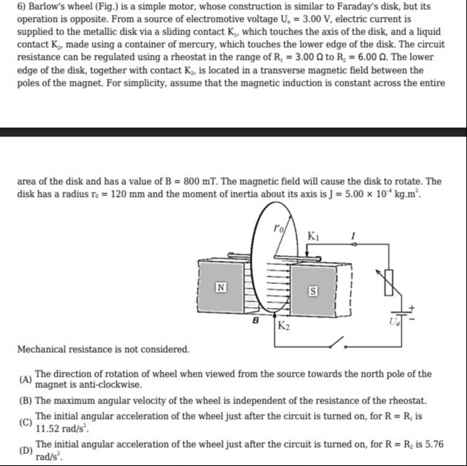
Barlow's wheel (Fig.) is a simple motor, whose construction is similar to Faraday's disk, but its operation is opposite. From a source of electromotive voltage Ue = 3.00 V, electric current is supplied to the metallic disk via a sliding contact K1, which touches the axis of the disk, and a liquid contact K2, made using a container of mercury, which touches the lower edge of the disk. The circuit resistance can be regulated using a rheostat in the range of R1 = 3.00 Ω to R2 = 6.00 Ω. The lower edge of the disk, together with contact K2, is located in a transverse magnetic field between the poles of the magnet. For simplicity, assume that the magnetic induction is constant across the entire area of the disk and has a value of B = 800 mT. The magnetic field will cause the disk to rotate. The disk has a radius r0 = 120 mm and the moment of inertia about its axis is J = 5.00 x 10⁻⁴ kg.m².
Mechanical resistance is not considered.
The direction of rotation of wheel when viewed from the source towards the north pole of the magnet is anti-clockwise.
The maximum angular velocity of the wheel is independent of the resistance of the rheostat.
The initial angular acceleration of the wheel just after the circuit is turned on, for R = R1 is 11.52 rad/s².
The initial angular acceleration of the wheel just after the circuit is turned on, for R = R2 is 5.76 rad/s².
A, B, C, D
Solution
The problem describes Barlow's wheel, a simple DC motor, and asks us to evaluate four statements regarding its operation.
Given Parameters:
- Electromotive voltage, Ue=3.00V
- Resistance range, R1=3.00Ω to R2=6.00Ω
- Magnetic induction, B=800mT=0.8T
- Disk radius, r0=120mm=0.12m
- Moment of inertia, J=5.00×10⁻⁴kg⋅m2
- Mechanical resistance is neglected.
Evaluation of Statements:
(A) The direction of rotation of wheel when viewed from the source towards the north pole of the magnet is anti-clockwise.
- Current Direction: From the circuit diagram, the positive terminal of the battery is connected to K1 (axis) and the negative terminal to K2 (edge). Thus, current flows radially outwards from the axis to the edge of the disk.
- Magnetic Field Direction: The magnetic field lines go from the North (N) pole to the South (S) pole. In the figure, the N pole is on the left and the S pole is on the right, so the magnetic field B points horizontally to the right.
- Force Direction (Fleming's Left-Hand Rule): Consider the segment of the disk at the bottom where the mercury contact K2 is located. The current I flows radially outwards, which is downwards in the diagram. The magnetic field B is to the right.
- Align your forefinger (magnetic field) to the right.
- Align your middle finger (current) downwards.
- Your thumb (force) will point out of the page.
- Rotation Direction: An outward force on the lower part of the disk will cause it to rotate such that the bottom moves out of the page. If we view the wheel from the source side (right side) towards the North pole (left side), an outward motion of the bottom edge corresponds to an anti-clockwise rotation. Therefore, statement (A) is correct.
(B) The maximum angular velocity of the wheel is independent of the resistance of the rheostat.
- Induced EMF (Back EMF): As the disk rotates with angular velocity ω, the radial conductors cut magnetic field lines, inducing a back EMF. The induced EMF Ui across the radius of the disk is given by: Ui=21Br02ω
- Circuit Equation: According to Kirchhoff's voltage law, the net voltage causing current flow is Ue−Ui. So, the current I in the circuit is: I=RUe−Ui
- Maximum Angular Velocity: When the disk reaches its maximum angular velocity (ωmax), it enters a steady state where the net torque becomes zero (since mechanical resistance is neglected). This happens when the induced back EMF equals the applied voltage, causing the current I (and thus the driving torque) to become zero. So, Ui=Ue 21Br02ωmax=Ue ωmax=Br022Ue
- Dependence on Resistance: The expression for ωmax depends on Ue, B, and r0, but it does not depend on the resistance R. Therefore, statement (B) is correct.
(C) The initial angular acceleration of the wheel just after the circuit is turned on, for R = R1 is 11.52 rad/s². (D) The initial angular acceleration of the wheel just after the circuit is turned on, for R = R2 is 5.76 rad/s².
-
Initial Conditions: Just after the circuit is turned on, the disk is at rest, so its angular velocity ω=0. This means the induced back EMF Ui=0.
-
Initial Current: The initial current Iinitial in the circuit is determined solely by the applied voltage and the total resistance: Iinitial=RUe
-
Torque on the Disk: The magnetic force on the current flowing through the disk creates a torque. The torque τ on the disk is given by: τ=21IBr02 Substituting Iinitial: τinitial=21(RUe)Br02=2RUeBr02
-
Angular Acceleration: According to Newton's second law for rotation, the angular acceleration α is given by τ=Jα, so: αinitial=Jτinitial=2JRUeBr02
-
Calculate for R1: For R1=3.00Ω: α1=2×(5.00×10−4kg⋅m2)×(3.00Ω)(3.00V)×(0.8T)×(0.12m)2 α1=2×5.00×10−4×3.003.00×0.8×0.0144 α1=0.0030.03456 α1=11.52rad/s2 Therefore, statement (C) is correct.
-
Calculate for R2: For R2=6.00Ω: Since αinitial is inversely proportional to R: α2=α1×R2R1 α2=11.52rad/s2×6.00Ω3.00Ω α2=11.52×21 α2=5.76rad/s2 Therefore, statement (D) is correct.
All four statements (A), (B), (C), and (D) are correct.
Explanation of the solution:
- Direction of Rotation (A): Apply Fleming's Left-Hand Rule. Current flows radially outwards (downwards in the relevant section). Magnetic field is from N to S (rightwards). Force on the current-carrying segment is out of the page. This force causes an anti-clockwise rotation when viewed from the source side.
- Maximum Angular Velocity (B): At steady state (maximum angular velocity and neglecting mechanical resistance), the induced back EMF (Ui=21Br02ω) balances the applied voltage (Ue). Thus, Ue=21Br02ωmax, which gives ωmax=Br022Ue. This expression is independent of the circuit resistance R.
- Initial Angular Acceleration (C, D): Initially, ω=0, so back EMF is zero. The initial current is Iinitial=Ue/R. The torque is τinitial=21IinitialBr02=2RUeBr02. The initial angular acceleration is αinitial=τinitial/J=2JRUeBr02.
- For R1=3.00Ω, α1=2×5.00×10−4×3.003.00×0.8×(0.12)2=11.52rad/s2.
- For R2=6.00Ω, α2=2×5.00×10−4×6.003.00×0.8×(0.12)2=5.76rad/s2.