Question
Question: An electrical circuit is shown in figure. Calculate the potential difference across the resistor of ...
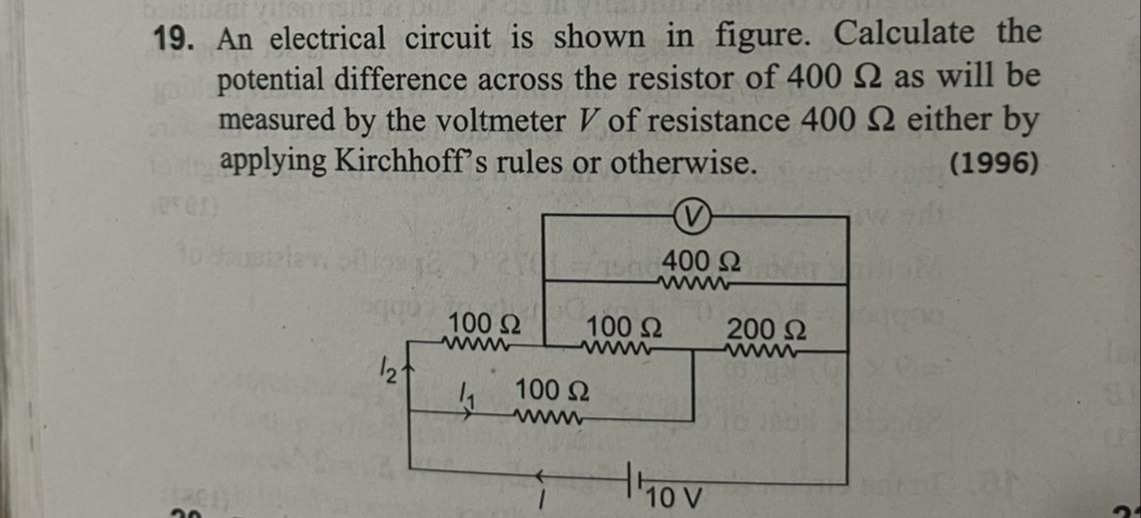
An electrical circuit is shown in figure. Calculate the potential difference across the resistor of 400 Ω as will be measured by the voltmeter V of resistance 400 Ω either by applying Kirchhoff's rules or otherwise.
20/3 V
Solution
The circuit diagram can be interpreted as follows:
A 10V battery is connected between two points. Let the positive terminal be at potential 10V and the negative terminal at 0V. Let the positive terminal be connected to a junction C. From C, there are two branches.
Branch 1: A 100 Ω resistor to junction D. From D, a 100 Ω resistor to junction E and a 200 Ω resistor to junction E. So, 100 Ω and 200 Ω are in parallel between D and E.
Branch 2: A 100 Ω resistor to junction F. From F, a 400 Ω resistor is connected to junction E. The voltmeter of resistance 400 Ω is in parallel with the 400 Ω resistor, so it is also connected between F and E. Junction E is connected to the negative terminal of the battery.
Let's redraw the circuit based on this interpretation. Battery (10V) connected between C (10V) and E (0V). From C, a 100 Ω resistor goes to D. From C, a 100 Ω resistor goes to F. From D, a 100 Ω resistor goes to E. From D, a 200 Ω resistor goes to E. From F, a 400 Ω resistor goes to E. From F, a 400 Ω voltmeter goes to E.
This interpretation also doesn't match the current labels in the diagram.
Let's go with the interpretation from the detailed thought process that matches the current labels and the connection points. Let the negative terminal of the battery be at node A (potential 0V). Let the positive terminal of the battery be at node B (potential 10V). From B, a wire goes to node C. From C, there are two branches.
Branch 1: A 100 Ω resistor to node D. Let the current be I1. Branch 2: A 100 Ω resistor to node E. Let the current be I2. So, the total current from the battery is I=I1+I2. This is consistent with the diagram.
From node D, there is a 100 Ω resistor to node F and a 200 Ω resistor to node G. From node E, there is a 400 Ω resistor to node F. The voltmeter is in parallel with the 400 Ω resistor, so it is also between E and F. Node F and G are connected to node A (0V).
Let's redraw the circuit based on this interpretation. Battery (10V) is connected between A (0V) and B (10V). From B to C (wire). From C to D: 100 Ω. From C to E: 100 Ω. From D to F: 100 Ω. From D to G: 200 Ω. From E to F: 400 Ω. Voltmeter (400 Ω) is between E and F. F is connected to A. G is connected to A.
The circuit is as follows:
Nodes are A, B, C, D, E, F, G. VA=0, VB=10. Wire BC. So VC=VB=10. Resistor 100 Ω between C and D. Resistor 100 Ω between C and E. Resistor 100 Ω between D and F. Resistor 200 Ω between D and G. Resistor 400 Ω between E and F. Voltmeter (400 Ω) between E and F. Wire FA. So VF=VA=0. Wire GA. So VG=VA=0.
We need to find the potential difference across the 400 Ω resistor, which is connected between E and F. This potential difference is VE−VF=VE−0=VE. We need to find the potential at node E.
The resistors between D and the ground are 100 Ω (to F, which is at 0V) and 200 Ω (to G, which is at 0V). So, 100 Ω and 200 Ω are in parallel from D to ground. Their equivalent resistance is RDG=100+200100×200=30020000=3200Ω.
The resistor between E and the ground is the parallel combination of the 400 Ω resistor and the 400 Ω voltmeter. Their equivalent resistance is REF=400+400400×400=800160000=200Ω.
Now, consider the circuit from node C (10V) to the ground (0V). From C, there is a 100 Ω resistor to D, and from D, the equivalent resistance to ground is RDG=200/3Ω. So, the resistance of the branch C-D-ground is 100+200/3=(300+200)/3=500/3Ω. From C, there is a 100 Ω resistor to E, and from E, the equivalent resistance to ground is REF=200Ω. So, the resistance of the branch C-E-ground is 100+200=300Ω.
Now we have node C at 10V and ground at 0V. Two branches are connected from C to ground.
Branch 1: 100 Ω in series with the parallel combination of 100 Ω and 200 Ω. Total resistance R1=100+100+200100×200=100+3200=3500Ω.
Branch 2: 100 Ω in series with the parallel combination of 400 Ω and 400 Ω. Total resistance R2=100+400+400400×400=100+200=300Ω.
Let I1 be the current in Branch 1 and I2 be the current in Branch 2.
I1=R1VC−Vground=500/310−0=50010×3=50030=503A.
I2=R2VC−Vground=30010−0=30010=301A.
We need to find the potential difference across the 400 Ω resistor, which is VE−VF. In Branch 2, the current I2 flows through the 100 Ω resistor from C to E.
VC−VE=I2×100.
10−VE=301×100=310.
VE=10−310=330−10=320V.
The potential at F is 0V.
The potential difference across the 400 Ω resistor (and the voltmeter) is VE−VF=320−0=320V.
Alternatively, consider the voltage division in Branch 2. The voltage across the parallel combination of 400 Ω and 400 Ω is the potential difference between E and F. The total voltage across Branch 2 is VC−VF=10−0=10V. This voltage is divided between the 100 Ω resistor (C to E) and the parallel combination of 400 Ω and 400 Ω (E to F). The equivalent resistance of the parallel combination is REF=200Ω. The resistance of the 100 Ω resistor is RCE=100Ω. The voltage across the parallel combination (E to F) is given by voltage division:
VEF=(VC−VF)×RCE+REFREF=10×100+200200=10×300200=10×32=320V.
So, the potential difference across the 400 Ω resistor is 320V.
Explanation of the solution:
- Interpret the circuit diagram and identify the nodes and components.
- Assume potentials at the battery terminals (0V and 10V).
- Identify the points between which the potential difference is to be measured (across the 400 Ω resistor, which is in parallel with the voltmeter). Let these points be E and F.
- Simplify the circuit by combining series and parallel resistors.
- Calculate the equivalent resistance of the parallel combination of the 400 Ω resistor and the 400 Ω voltmeter, which is 200 Ω. This combination is between nodes E and F.
- Identify the branch containing the 400 Ω resistor. This branch consists of a 100 Ω resistor in series with the parallel combination of the 400 Ω resistor and the voltmeter. This branch is connected between node C (at 10V) and node F (at 0V).
- Apply voltage division to find the voltage across the parallel combination of the 400 Ω resistor and the voltmeter. The total voltage across this branch is 10V. The resistance of the 100 Ω resistor is 100 Ω, and the equivalent resistance of the parallel combination is 200 Ω.
- The voltage across the parallel combination (between E and F) is 10×100+200200=10×300200=10×32=320V.
- This potential difference is the voltage measured by the voltmeter across the 400 Ω resistor.