Question
Question: In the circuit shown in the following figure, the potential difference cross 3µF capacitor is ...
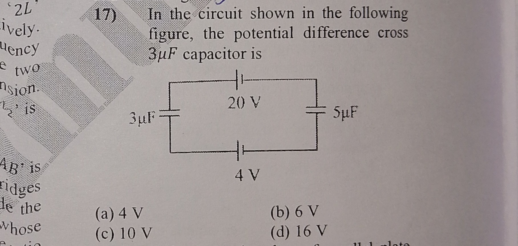
In the circuit shown in the following figure, the potential difference cross 3µF capacitor is
A
4 V
B
6 V
C
10 V
D
16 V
Answer
10 V
Explanation
Solution
-
For series capacitors, the same charge Q develops on both. The voltage across the 3 µF capacitor is
V3=3Q,and across the 5 µF capacitor is
V5=5Q. -
Applying Kirchhoff’s Voltage Law (KVL) around the loop:
20V−V3−V5−4V=0⇒V3+V5=16V. -
Substitute the capacitor voltage expressions:
3Q+5Q=16⇒Q(155+3)=16⇒Q(158)=16. -
Solving for Q:
Q=16×815=30μC. -
Now, voltage across the 3 µF capacitor:
V3=3μF30μC=10V.